 Featured Categories
RCCB SVL1M-63
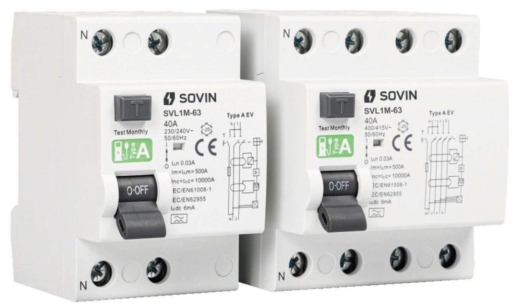
Specification:
| Electrical Features | |
| Mode | Electromagnetic |
| Type (wave form of the earth leakage sensed) | B |
| Rated Current In | 25, 40, 63A |
| Poles | 2P, 4P |
| Rated Voltage Ue | 2P 240V~, 4P 415V~ |
| Insulation Voltage Ui | 500V |
| Rated Frequency | 50/60Hz |
| Rated Residual Operation Current (I△n) | 30mA |
| Rated Residual Operating Current (I△dc) | 6mA |
| Rated Residual Making & Breaking Capacity (I△m) | 500A (In≤40A), 10In (In>40A) |
| Short-circuit Current Inc = I△c | 10000A |
| SCPD Fuse | |
| Break Time Under I△n | ≤0.1s |
| Rated Impulse Withstand Voltage (1.5/50) Uimp | 4000V |
| Dielectric Test Voltage at ind.Freq. for 1min | 2.5kV |
| Electrical Life | 2000 Cycles |
| Mechanical Life | 4000 Cycles |
| Installation | |
| Contact Position Indicator | Yes |
| Protection Degree | IP20 |
| Ambient Temperature (with daily average≤35℃) | -25℃~+35℃ |
| Storage Temperature | -25℃~+70℃ |
| Terminal Connection Type | Cable/Pin-type Busbar/U-type Busbar |
| Terminal Size top/bottom for Cable | 35mm2 18~3AWG |
| Terminal Size top/bottom for Busbar | 35mm2 18~3AWG |
| Tightening Torque | 2.5Nm 22In-lbs |
| Mounting | On DIN Rail EN60715(35mm) by means of fast clip device |
| Connection | Power Supply in Both Directions |
Tripping Current Range:
| Lagging Angle | I△n>0.01A | I△n≤0.01A |
| 0° | 0.35I△n ≤ I△ ≤ 1.4I△n | 0.35I△n ≤ I△ ≤ 2I△n |
| 90° | 0.25I△n ≤ I△ ≤ 1.4I△n | 0.25I△n ≤ I△ ≤ 2I△n |
| 135° | 0.11I△n ≤ I△ ≤ 1.4I△n | 0.11I△n ≤ I△ ≤ 2I△n |
| Alternative Current Sensitive | Pulsating Direct Current Sensitive | Surge Current Proof |
| B Class Tripping is ensured for sinusoidal AC residual currents pulsed DC residual current, alternating residual sinusoidal currents up to 1000Hz, pulsating direct residual currents and for smooth direct residual currents, whether applied suddenly or increasing slowly. | They react to AC and pulsating DC fault current which reach 0 or almost 0 within one time period of the mains frequency. | RCCB’s surge capacity. Not tripping at standardized 8/20 us surge-current waves acc.to VDE 0432 Part 2 with surge current values of up to 250A. |
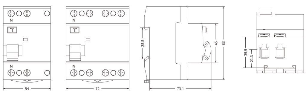
Overall and Installation Dimension (mm)
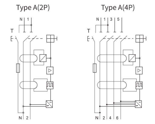
Circuit Diagram
Related recommendations
-

NDQ3-250
8791.Applicable Scope and Purpose The NDQ3-250 P-grade ATSE are applicable for sites with the AC voltage below AC380V.AC400V.AC415V and the rated frequency of 50Hz. This product complies w...
View details -
LV Switchgear
24Overview LV Switchgear, also known as UL 1558 Low Voltage Switchgear, is a key low-voltage power distribution product used for receiving, distributing, controlling, and protecting electrical en...
View details -
NDM2E-400
9271. Applicable Scope and Purpose of Circuit Breaker The NDM2E-400 series of electronic molded case circuit breakers (hereinafter referred to as circuit breakers) apply to infrequent swit...
View details -
NDG2-200 3P Isolating Switch
933Applications: NDG2-200/3 Switch Disconnector is applicable to the low-voltage distribution or motor network under AC 50Hz, rated working voltage of AC400V and AC690V and rate...
View details


HelloPlease log in